FreeCore Function #12:
MII Management
Interface Controller
Module name: mii
Current
release: version 1.0, August 20, 1997
Contributed by: Woody
Johnson woodyj@dacmail.net
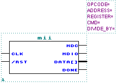
Shown below is the schematic representation of the module:

This is a design that can be used to read or write a register value as defined by the IEEE 802.3 MII Management Interface. For instance - all 100Mb Ethernet PHYs with an MII interface have a serial management port with several registers that can be accessed by this design.
The design operates immediately upon negation of the input reset signal and proceeds to commence a one time read or write command sequence as determined by module parameters.
| PARAMETERS | |
| OPCODE | "READ" or "WRITE". |
| ADDRESS | 0-31. This value selects the PHY, or destination of the access. |
| REGISTER | 0-31. This value selects the register to access. |
| CMD | 0-FFFF. This is the value written to the register (if "WRITE" opcode selected). |
| DIVIDE_BY | >0. Clk input frequency is divided by 2^DIVIDE_BY to generate MDC clock frequency. This should be chosen to result in a frequency <= 2.5MHz. |
| INPUT PORTS | |
| Clk | System clock input. More than 75MHz is possible using a MAX7K-15 device. |
| /Rst | Asynchronous low-active reset. |
| OUTPUT PORTS | |
| MDC | Management Data Clock. |
| MDIO | Management Data Input/Output. |
| Data[15..0] | Data value read from or written to device. |
Enjoy!
![]()
Last
updated 08 Feb 2001 11:53